We address the task of generating the 2D flow of a target object and the corresponding end-effector trajectory for robotic manipulation , guided by a pre-manipulation RGB image and a language instruction.
Flow-based methods, which predict both 2D flow and trajectories from language and initial images, offer significant advantages: they can adapt to various daily tasks using only a small amount of real-robot data and can be trained on readily available web videos depicting object manipulation. However, there is a scarcity of multimodal flow-based methods trained on large datasets. Furthermore, many existing approaches employ closed-loop trajectory generation, which necessitates more demonstration data and suffers from error accumulation. To overcome these limitations, we propose LILAC , a flow-based Language Instruction-guided open-Loop ACtion generator, a novel multimodal flow-based model capable of offline trajectory generation.
Our contributions include introducing
Experimental results demonstrate that our method generates higher quality flow compared to existing approaches and achieves superior task success rates in real-robot object manipulation tasks.
We tackle the task of predicting whether a tabletop object manipulation task was performed successfully, given the instruction sentence and ego-centric images taken before and after the manipulation. We define this task as Success Prediction for Object Manipulation (SPOM).
Fig. 1: Typical samples of SPOM task. The each top sentence is the given instruction for each sample. The top and bottom images depict the scene before and after the manipulation, respectively.
To tackle the task, we propose the novel approach to create the multi-level aligned representations for images, and build the success prediction method based on them—Contrastive \(\boldsymbol \lambda\)-Repformer.
Fig. 2: Overview of Contrastive \(\lambda\)-Repformer. Given an instruction sentence and images before and after manipulation, our model outputs the predicted probability that the robot successfully performed the manipulation.
Fig. 3: \(\boldsymbol \lambda\)-Representation—the multi-level aligned visual representation composed of three types of latent representations: features that capture visual characteristics such as colors and shapes (Scene Representation), features aligned with natural language (Aligned Representation), and features structured through natural language (Narrative Representation).
The Scene Representation \(\boldsymbol{h}_s\) is obtained by concatenating the outputs of several unimodal image encoders (e.g.: ViT, Swin Transformer, DINOv2).
We get Aligned Representation \(\boldsymbol{h}_a\) using the Aligned Representation Module, which is composed of multimodal foundation models such as CLIP, SigLIP and BLIP.
Narrative Representation \(\boldsymbol{h}_n\) is obtained using the Narrative Representation Module, containing MLLMs (e.g.: InstructBLIP, Gemini, GPT-4) and text embedders (e.g.: BERT, text-embedding-ada-002). We designed the text prompt to focus on the colors, sizes and shapes of the target objects, how they are placed, their position within the image and relative position to other objects. From the output of MLLMs, we acquire its features using text embedders. Then, they are concatenated to get \(\boldsymbol{h}_n\).
Finally, we obtain the \(\boldsymbol \lambda\)-Representation by concatenating the three representations: \[\boldsymbol{h}_{\lambda}=\left[\boldsymbol{h}_s^\mathsf{T}, \boldsymbol{h}_a^\mathsf{T}, \boldsymbol{h}_n^\mathsf{T}\right]^\mathsf{T}.\]
The differences between the images do not by themselves necessarily indicate the success of the task specified by the instructions. To address this issue, we propose the Contrastive \(\lambda\)-Representation Decoder, which use cross attention based architecture to obtain the predicted probability \(P(\hat{y}=1)\), indicating the probability that the manipulator has successfully executed the task.
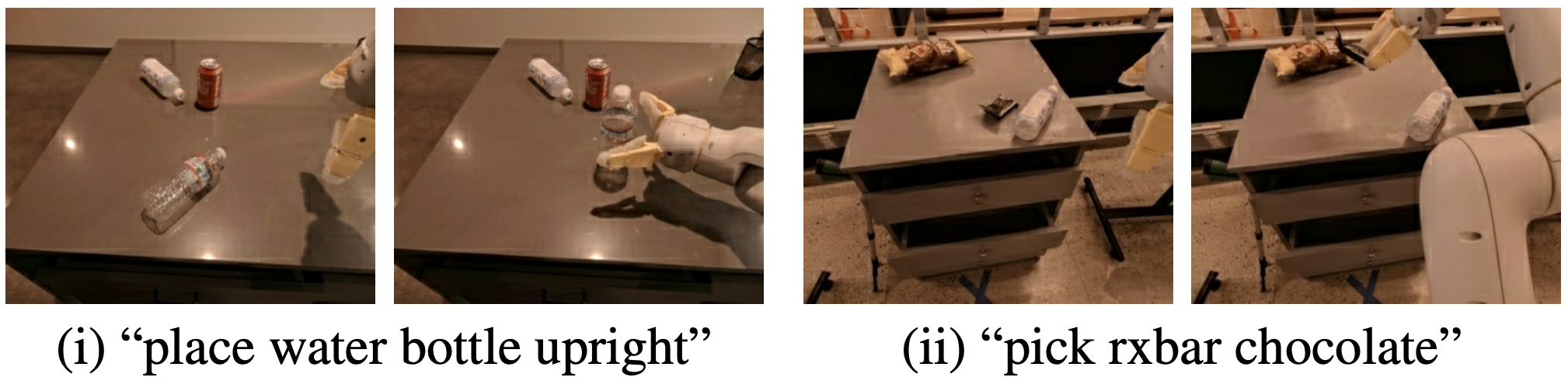
Fig. 4: Successful cases of the proposed method from SP-RT-1: The left and right images show the scene before and after
the manipulation, respectively.
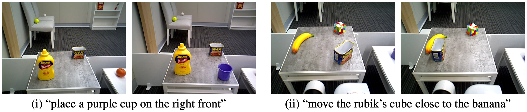
Fig. 5: Qualitative results of the proposed method in zero-shot transfer experiments. The left image depicts
the scene before the manipulation, while the right image shows it afterward. Examples (i) and (ii) are true
positive and true negative cases, respectively.
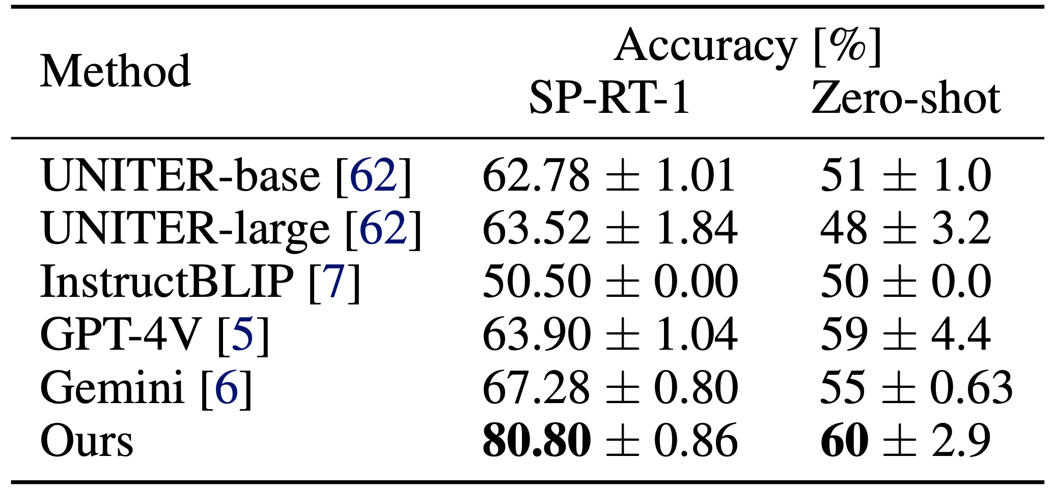
Table 1: Quantitative results. The best results are marked in bold.
To be appeared.